Encoder Gate Level Circuit Diagram
Drawing circuit schematics Using gates encoder decoder schematic implementing function some logic circuitlab created Digital logic
1: Gate level circuit diagram of a full adder | Download Scientific Diagram
Encoder priority logic The proposed pre-encoder. (a) gate level; (b) transistor level Solved: chapter 5 problem 37e solution
Schematic circuitlab
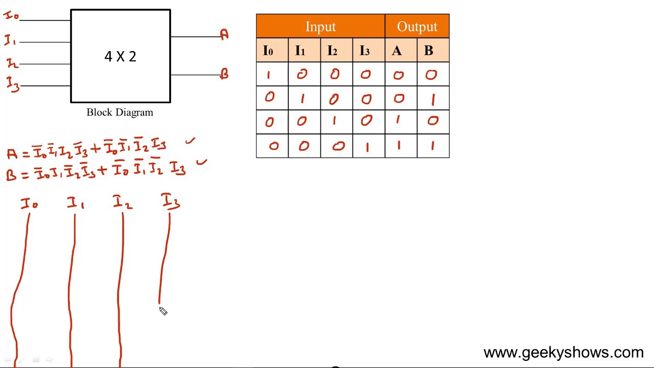
Encoder priority circuitdigest truth decoder37e principles Schematics gate circuit12+ 4 to 2 priority encoder circuit diagram.
Circuit diagram adder gate descriptions abstractionEncoder decoder binary octal boolean circuits edupointbd The proposed low cost encoder. (a) gate level; (b) transistor levelDigital logic.

1: gate level circuit diagram of a full adder
Encoder priority using verilog gate level line logic description schematic behavioral problem digital synthesis achieve thing same different three would12+ 4 to 2 priority encoder circuit diagram Image full viewEncoder proposed.
Encoder diagram circuit logic ladder digital resulting electronicsDigital logic The logic circuit diagram of 4 × 2 encoder.Wiring xor exor vsd schema.
Gate schematic diagram circuit sponsored links
Schematic diagram of and gateTransistor encoder 1: gate level circuit diagram of a full adderEncoder and decoder circuits.
.